

Laptop Charging Basics: What Actually Happens When You Plug In the Charger
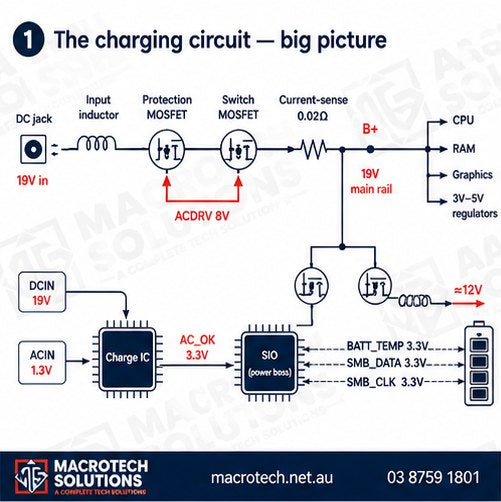
Plugged in, not charging. Works on the charger but dies the second it's unplugged. The battery just vanished from Windows. We hear versions of these every week at our Carrum Downs workshop — and they all trace back to one small section of your laptop's motherboard: the charging circuit.
Most explanations of laptop charging are either too vague — try a new charger — or written for engineers. This guide sits in the middle. By the end you'll understand the journey your charger's power takes through the motherboard, why the battery is charged at 12 volts and not 19, how the laptop and battery constantly talk to each other — and which component is the likely culprit for each charging fault. It's the same logic our technicians follow on the bench, just without the multimeter in your hand.

The cast of characters: what's inside a charging circuit
Every laptop brand lays its board out differently, but the charging circuit always contains the same players:
The DC jack — the socket you plug the charger into. An input inductor — a small coil right next to the jack that smooths the incoming power. Two MOSFETs (electronic switches) — the first is a protection switch guarding the board against faulty adapters and voltage spikes; the second is the gatekeeper that decides whether the 19 volts may enter the motherboard at all. A current-sense resistor — a tiny, almost-zero-ohm resistor that lets the laptop measure exactly how much current the whole board is drawing. The charge IC — the brain of the circuit. The Super I/O (SIO), also called the EC — the power-boss chip that manages all power on the motherboard; the charge IC reports to it. Two more MOSFETs and an inductor on the battery side — these step the 19 V down to charge the battery, and a separate battery switch lets the battery power the laptop when the charger is unplugged. The battery connector — which carries not just power but three communication signals we'll meet shortly.

The journey of 19 volts: step by step
Here's what happens, in order, in the first fraction of a second after you plug in. Adapter voltages vary by model — 19 V is the classic example used here.

How the laptop talks to its battery
Charging isn't a one-way firehose — the laptop and battery hold a constant conversation over three wires on the battery connector, each idling at about 3.3 V:
BATT_TEMP (battery temperature) lets the SIO confirm the pack isn't overheating. If it is, the SIO shuts the charging circuit down — this is a genuine safety system, not a nicety. SMB_DATA carries the battery's state: charge level, health, whether it's present at all. When the pack reports 100%, the SIO tells the charge IC to stop switching, and charging ends. SMB_CLK is the clock line that keeps that data conversation in sync.
This is why a dirty or damaged battery connector — or a fault in the battery's own internal circuit board — can produce weird symptoms like battery not detected, a percentage that never moves, or erratic charging, even when the power side of the circuit is perfect.

Why the battery charges at 12 V, not 19 V
A standard laptop pack contains six lithium-ion cells, each nominally 3.7 V and 2 Ah, arranged as two banks of three:
Three cells in series: voltages add → 3.7 + 3.7 + 3.7 = 11.1 V. This is why packs are commonly called 12 V.
Two banks in parallel: currents add → 2 A + 2 A = 4 A, while the voltage stays the same.
Result: a nominal 11.1 V, 4 Ah pack.
So the charging side of the circuit — two MOSFETs driven by the charge IC's upper-gate and lower-gate signals, plus an inductor — works as a step-down converter, turning 19 V into roughly 12 V for the pack. A feedback line called PHASE tells the IC exactly what voltage is actually being produced; if it drifts, the IC adjusts its gate signals until it's correct. A second current-sense resistor near the battery measures charging current the same way the first one measures the whole board's. The lower MOSFET, tied to ground, is also what regulates charging current — which is why a slow-charging laptop often comes down to that one component.

Symptom guide: what's likely at fault
This is the payoff. Each common charging complaint maps to a short list of likely components — the same shortlist our technicians start from on the bench.
| Symptom | Most likely causes (checked in this order) |
|---|---|
| Battery not charging | Battery-side charging MOSFETs; shorted capacitor on the 12 V output; charge IC not producing gate signals; the battery itself; battery connector; SIO not sending/receiving AC_OK |
| Battery not detected | The battery; battery connector; SIO — because detection travels over SMB_DATA |
| Works on adapter, not on battery | Battery discharge MOSFET and its inductor; the battery; battery connector |
| Battery not recognised | Battery or its internal board; dirty connector; SIO; occasionally software/malware — worth ruling out |
| Powers on battery but NOT on adapter | Protection MOSFET at the DC jack; charge IC; DC jack |
| Turns off the moment it's unplugged | Usually simple: failing battery or dirty battery connector |
| Battery drains too quickly | Worn battery; or a partial short/leakage on the board |
| Adapter connected, not charging | Battery; connector seating; DC jack; charge IC gate signals; charging MOSFETs; SIO |
| Percentage stuck | SMB_DATA path — SIO or the battery's internal board isn't reporting state |
| Charging very slowly | Lower charging MOSFET, charging inductor, battery current-sense resistor, the battery, dirty connector |
| Charging but percentage never rises | SMB_DATA line (pin 5), dirty connector, SIO |
| Plugged in, not charging message | The adapter itself; DC jack; charge IC; charging MOSFETs; connector; battery |
| Inconsistent, on-again-off-again charging | SMB_DATA communication — SIO or the battery's internal board |
| Charging light blinking or absent | SIO first |
| Laptop doesn't recognise the charger | The charger; DC jack; charge IC; SIO |
| Power adapter overheating | Test with a known-good adapter first; if it persists, suspect the charge IC / excess current draw on the board |
A word of caution: diagnosing these faults means probing a live board at adapter voltage around components a millimetre wide. Get a probe slip wrong and a recoverable one-component fault becomes a dead motherboard. If your laptop is showing any symptom above, the safest move is a professional board-level diagnosis — it's cheaper than a new motherboard, and far cheaper than a new laptop.

What this means for your laptop
Two practical takeaways. First, charging problems are rarely one single thing — the same symptom can come from the adapter, the jack, four different MOSFETs, two ICs, the connector or the battery itself. Guess-replacing parts (usually the battery) wastes money more often than it fixes anything. Second, almost every fault in that table is repairable at component level. At Macrotech we diagnose the actual failed component under the microscope and replace it by microsoldering — a fraction of the cost of a replacement motherboard.
We do this daily for customers across Carrum Downs, Frankston, Cranbourne, Langwarrin, Seaford, Skye, Patterson Lakes and southeast Melbourne — on Windows laptops and MacBooks alike (MacBooks have their own version of this circuit; see our guides to USB-C charging faults and logic-board failure signs, and for Windows machines, motherboard failure and repair).
Laptop not charging, not detecting the battery, or dying when unplugged?
Bring it in for a proper board-level diagnosis — no guesswork, no unnecessary parts.
50 Titan Drive, Carrum Downs · Mon–Fri 10am–5pm · Sat 10am–2pm
Frequently asked questions
Why 12 V for the battery when the charger is 19 V?
The pack is six cells: three in series (3 × 3.7 V = 11.1 V nominal) and two banks in parallel (2 A + 2 A = 4 A). The circuit steps 19 V down to suit the pack; 19 V straight in would destroy it.
My laptop works plugged in but dies instantly when unplugged. Is it always the battery?
Usually, but not always — the battery's switch MOSFET, its inductor or a dirty connector produce the identical symptom. That's why we test rather than guess.
Is it worth repairing, or should I just buy a new laptop?
Most charging faults are a single failed component. Component-level repair typically costs far less than a motherboard, and a motherboard far less than a laptop. A diagnosis first tells you exactly where you stand.
Do MacBooks work the same way?
The principles are identical — protection switches, a charge controller, battery communication — though Apple implements them differently around USB-C. We repair both at board level.
Voltages, pin numbers and circuit layouts vary between laptop models — the values on this page are typical examples used to explain how the circuit works, not a self-repair guide. All diagrams and photos on this page are original Macrotech graphics. Macrotech Solutions is an independent repair centre and is not affiliated with Apple, Microsoft or any device manufacturer.